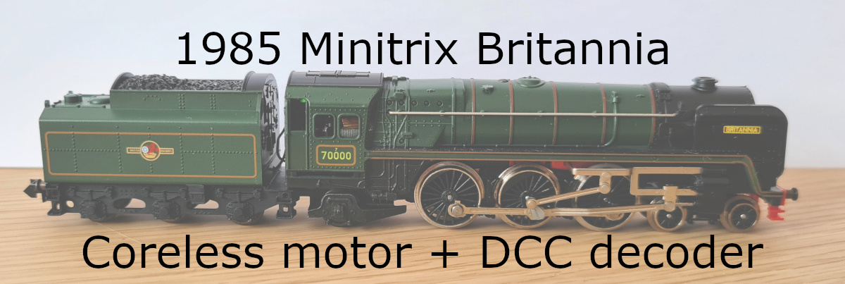
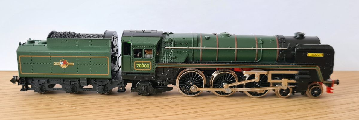
Several years ago I purchased a Minitrix Britannia as my first N gauge locomotive. It was the second version they produced as described here. It was in great cosmetic condition and ran well. Surprisingly well, in fact, for a second-hand purchase by someone new to N gauge model railways. My later second-hand purchases would be… unfortunate. But that’s a different story. My Britannia saw plenty of use pulling British Rail Mark 1 coaches around whenever I could get my track set up. At the time it hit the perfect balance between being a nice model, a good runner, and not so expensive that I worried about my kids potentially damaging it.
As I gathered more rolling stock, the Britannia started to come out less. That was partly because models of diesel or electric locomotives simply tend to be more robust and easier to rail than steam ones. The newer models also had better slow speed performance and the various other qualities you get from a model that isn’t 40 years old. Given that I wasn’t relying on the Britannia so heavily anymore, I had an interesting thought—how hard would it be to upgrade it with a coreless motor to give it a new lease of life? I had also started dabbling in DCC control, so I decided “in for a penny, in for a pound” and took a look to see if it could also have DCC control capability added to it. If I was going to be opening it up and replacing parts anyway…
Parts list
I fairly quickly found that Tramfabriek had a coreless motor upgrade kit for the Britannia. Their installation instructions also point to some Train-O-Matic DCC decoders they sell with the notes that “A decoder would fit behind the replacement motor” and “if you use the tiniest ones available, it would even fit under the motor frame”. Remember those sentences, I’ll come back to them. I decided to get a motor filter as well, because why not? I would also need to replace the existing front light with an LED. I took to Amazon to look for suitable ones, but of course your favourite electronics supplier will almost certainly stock them.
With the sources of my parts identified, I made a list:
- Tramfabriek Britannia & Mallard 12V coreless motor upgrade kit (SKU: MTBRIT). See the item listing and the installation instructions.
- Train-O-Matic Lokommander 2 Micro with bare wires (SKU: 02010223). See the item listing.
- Train-O-Matic motor filter for DCC (SKU: 02020301, 5 pieces). See the item listing.
- 3mm warm white LED. I bought a large set of different colour LEDs. The listing is here, now out of stock, but any of this size and colour will do.
- Wire as needed. I selected some appropriate colours from here.
- Kapton tape (or equivalent polyimide tape), for insulating exposed contacts and suchlike.
- Heatshrink.
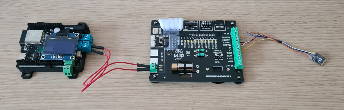
To avoid the situation of doing all the wiring and then finding out I received a faulty decoder, I also purchased a tester:
- Tramfabriek DCC Decoder Test Board (SKU: DT200). See the item listing.
Though note that the LED outputs on the Lokommander 2 Micro do not have current limiting resistors and I’m unsure whether the tester board does, so be careful with running the onboard LEDs on the tester. I added a resistor myself when hooking it up just to be safe.
Preparing the locomotive
The first step was, of course, to open up the locomotive and remove any parts that would no longer be needed. The Britannia is quite easy to take apart, with just a single screw holding the body shell on. I made the choice of keeping all the modifications within the locomotive itself, leaving the tender as-is. Two key factors in that decision were that the tender seemed more fiddly internally, whereas I knew how to handle the internals of the locomotive, and that I didn’t want to have to run a bundle of wires between the two.
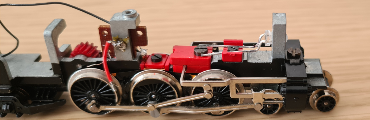
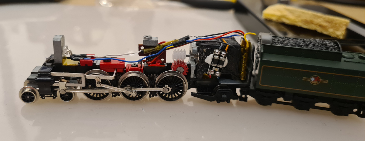
First, I removed the motor and did a quick test of where the decoder could be reasonably fitted. I immediately discovered that the statements that the decoder would fit behind the motor, or even underneath it, were simply not true. There didn’t seem to be a sensible way to fit the decoder under the motor at all, and the only way I could fit it behind the motor was to carefully cut off the (fairly thick) protective sleeve it comes in and wrap it in Kapton tape instead. Let me tell you, cutting that sleeve off while trying not to damage the wires or the board was… an experience. With that done, I could slip the decoder in behind the motor. It’s still very tight—it presses on the wires coming out of the motor, the motor is fractionally further forward than it really wants to be, and the locomotive body shell presses on the wires coming out of the decoder. But, it does fit.
With the decoder position figured out, I resumed stripping the locomotive. I removed the existing front lightbulb, the various contacts that fed power to the bulb, and the capacitor/choke combo.
[removed parts. Caption: These parts were no longer needed.]
Test fitting
Before starting to actually fit the new parts, I did a test fit. I actually did a lot of test fits trying out different things before I committed. I wanted to make sure I had a good plan and wasn’t going to get it all wrong.
One issue I encountered was that my 3mm LEDs were very slightly too large to fit through the hole the original bulb sat in. I had previously tried with a different 3mm LED and it had just squeezed in, so the hole must have been right on the edge of the tolerances and my new LEDs were just on the wrong side. I didn’t relish the idea of making the hole larger, so I took the next best option and filed down the LED a little. I carefully took a little material off evenly around it and eventually got it slotting into the hole. I also had to make sure that there was clearance for the leads and wires now that I was no longer using the original contacts. Luckily there was just enough space in front of the weight to bend the leads straight down and then the wires could follow a channel beneath the weight. The wires don’t like fitting under there, but I made it mostly work.
The only remaining piece of the puzzle was the motor filter. I fairly quickly decided that the best option to allow sensible routing of the wires would be to stick it to the side of the motor housing.
Fitting
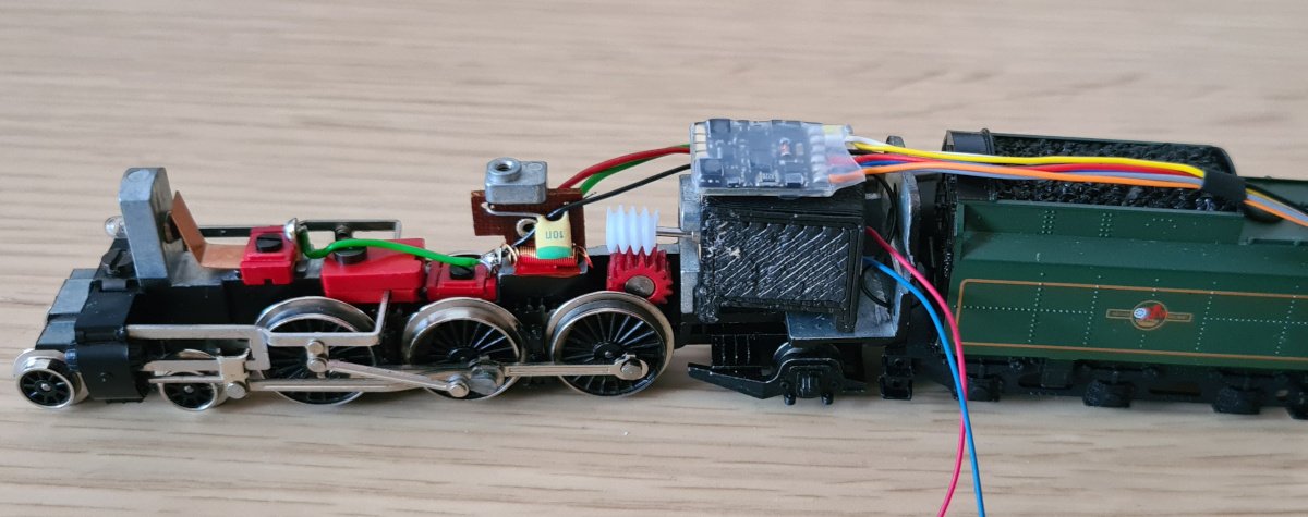
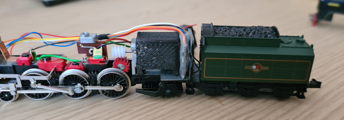
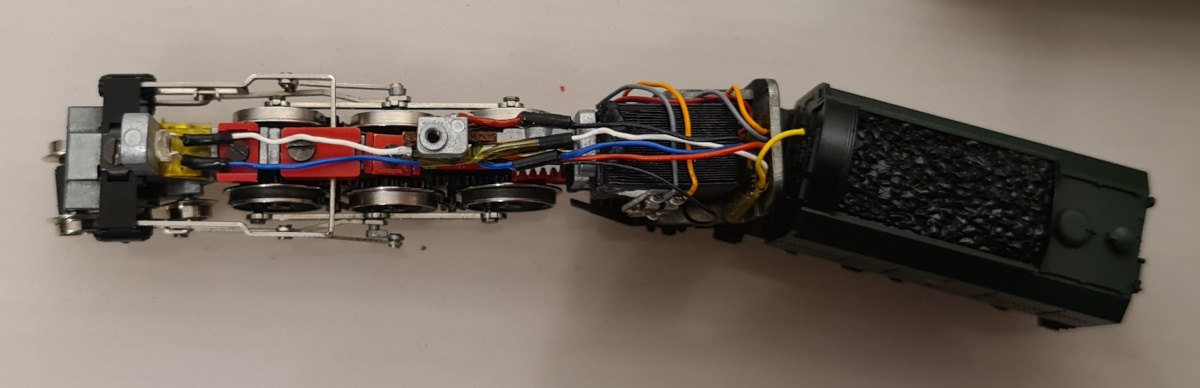
At this point I was ready to start putting the parts in for real. The first thing to go in was the new motor. It was the largest part and the motor filter would be stuck to the side of it. I applied Kapton tape to everything metallic that would be near the new components. This primarily meant any surfaces near the LED leads, the plate behind the decoder, and the decoder itself. The decoder is not stuck down and is simply a friction fit behind the motor. The LED is held in place by a small dab of glue and the weight behind pressing on the leads. At this point I had everything in place. I soldered the LED wires before all the others, leaving them long for now. I didn’t want to attempt to trim them to the exact length needed and then find I’d miscalculated, so I used the entire wire from the decoder with the intention of cutting and shortening the wire nearer the decoder end once the rest of the fitting was progressing.
I gathered my courage and started cutting and soldering the wires. I also melted a bit of plastic here and there trying to cut a corner or two, but nothing of any importance. No use crying over spilt milk, right? I had aligned the motor filter such that the wires from the decoder to it and from there to the motor could wrap neatly around the motor housing. I simply cut off the decoder rear light and auxiliary wires as they were not being used.
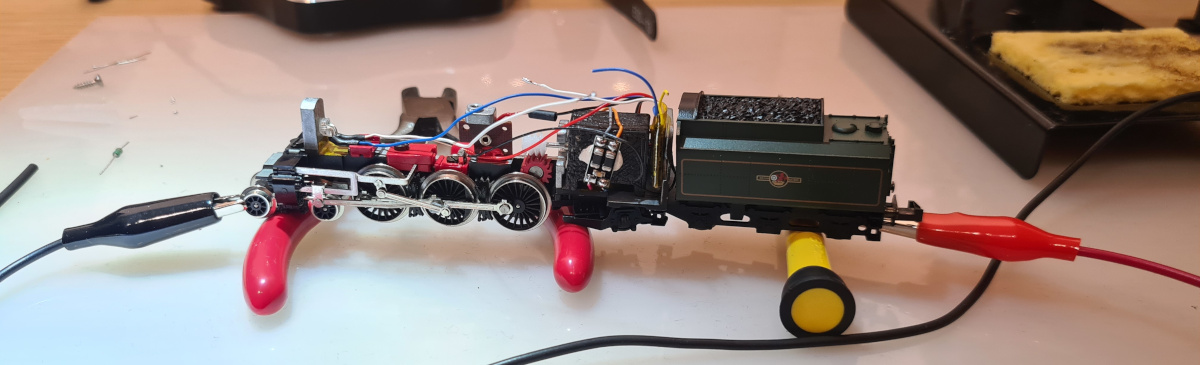
Once the rail connections for the decoder were connected, I gave the decoder a quick test to make sure I hadn’t made any silly mistakes. This involved sitting the locomotive on some tools to lift the driving wheels up and then using little crocodile clips onto appropriate pickup wheels to connect back to the tester. When instructed the motor to turn, it did so briefly and then things seized up. After a brief panic, I manually rotated the motor back and forth while inspecting the gears and noticed that a tiny bead of solder had fallen into the gears. After removing that, I tried again and the motor drove the wheels flawlessly. Suitably reassured, I continued with the finishing steps.
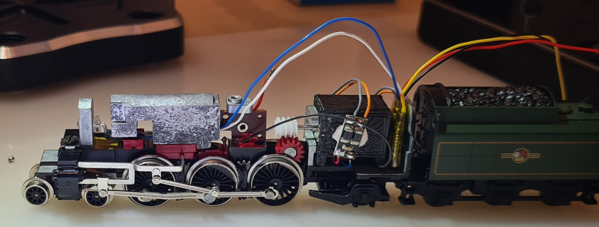
The remaining decoder wires had to bridge over the motor spindle and attached worm gear. I put the LED resistor in line here, providing a bit of structure that the other wires could be attached to so they didn’t sag onto the gear over time.
I then gave the locomotive, sans body shell, a brief run on some track using a DCC controller to confirm everything was electrically good. It was!
The last step was to fit the body shell back on. This was still an unknown. With most of the new parts being located in the cab, and the large number of wires concentrated there plus the bundle of wires running above the worm gear, it was going to be a tight fit. I hadn’t been able to check the fit prior to this as the wires completely prevented it until they were cut to size and correctly routed.
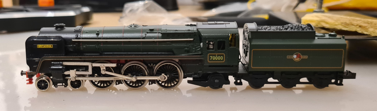
I placed the body shell on, and… it didn’t quite fit into place. With me worrying that the project was going to fail at the last hurdle, I did some fiddling and managed to convince it to get into the right position. I feel like it might be slightly high at the rear still, but looking at photos of other Minitrix Britannias that might just be how it is.
Final test
With the locomotive complete, I placed it on the track and started it up. I had confidence that this test would go well as I had already run the locomotive without the body shell, but there’s always a chance the reassembly had fouled something up. Fortunately it ran exactly as I had hoped.
[video?]
Conclusion
So, how do I feel about the project now that it’s complete? Honestly, I’m very happy with it. I was rather throwing myself in at the deep end with my first project being the upgrade of a 40 year old locomotive to have both a coreless motor and DCC control, but I think I pulled it off quite well. Having some prior electronics experience, and especially soldering experience, definitely helped a lot.
The running at the lowest speed settings isn’t up to modern standards as it’s still subject to the engineering of the rest of the mechanism, but it’s far superior to what it was capable of previously. It’s also very quiet, as you’d expect.